Tests and Analysis by David L. Ralph
© June 2008


The Seas 27TBCD/GB-DXT tweeter is a new one from Seas. From what I gather the DXT in the name is an acronym for Diffraction eXpansion Technology (caps mine). I just couldn't pass up buying a pair to test and put into a system. Only the tests are covered here. Following my normal procedure, I made an initial measurement on-axis to get a baseline, shown below.

First Thoughts on the Faceplate
The area of interest is above 13KHz and is primarily related to the diffraction in the horn and, to some degree, the rather large screw openings for mounting the faceplate/diaphragm assembly to the motor. I hesitate to call it a waveguide as I don't see it as being a true waveguide. It incorporates transition points (rings) that distinctly induce diffraction as a by-product of the design. My understanding of the intent of the design is to broaden the range of directional control, hence increasing the sensitivity, while maintaining smaller dimensions than would otherwise be required. This allows for a lower crossover point and/or reduced distortion due to lessened displacement needed for a given SPL on the design axis. The designer was successful in this regard, but there is a price to pay and that is the diffraction and what I'll call the breakpoints in the frequency response. Investigating the diffraction became my primary focus.
There's not much to learn from the cumulative spectral decay (CSD) or waterfall plot other than confirming the relatively insignificant resonances and, in this case, diffraction that are identifiable in the frequency response. There seems to be little in the way of resonances related to the area behind the dome. The damping in the pole-piece vent and the chamber do a commendable job controlling most reflections that normally result in resonances in the pole-piece vent.

Faceplate Diffraction
The DXT driver uses a faceplate design that incorporates four sections separated by the diffraction rings. These are easily seen and are the rings that are concentric to the diaphragm where there is a rather severe change in profile. These changes in profile have a somewhat drastic change acoustically that creates the breakpoints in the frequency response. This is the DXT® Lens licensed to Seas. Being symmetric about the axis and equidistant from the diaphragm, the rings have a significant impact on the frequency response.

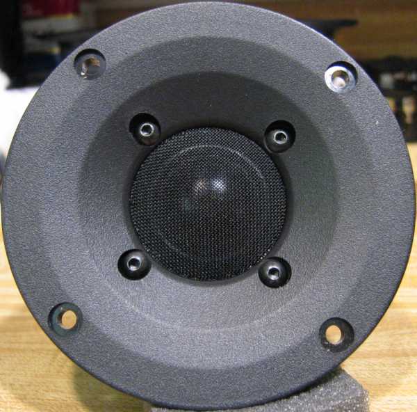

The wavelength corresponding to the first significant breakpoint at 13KHz, not surprisingly, coincided closely with the rough distance from the dome to the middle ring, the one a bit farther from the dome than the inner screw openings. At the same time I noticed that the openings for the screws that mount the faceplate to the motor were adjacent to this ring and seemed fairly significant in area and depth. I immediately filled in the gap for each screw opening with Blu-Tac and smoothed it to be flush with faceplate. It made more difference than expected. The response is shown below in yellow with the original response overlayed in blue.

Note the relatively broad area of impact. This would be due to the fact that the "distance" from the dome to the gap is in reality an integrated one from all points not occluded by other parts of the faceplate and/or dome itself. It's a complex one that also is affected by the angle of the ray emanating from each point on the dome to each point on the surface of the screw opening. Add to that the fact that in some cases it's diffraction at the opening and other cases it's a hard reflection from the far side of the opening. In the end, you get a ragged response from 13KHz to over 20KHz. The profile farther out from the middle ring works well with no glitches in the response. The farthest ring, the one at which the faceplate becomes flat and flush with the front, is roughly equivalent to a wavelength corresponding to the 6-7KHz range. The frequency response has a very minor bump in the response in the range that can also be seen in the CSD as very minor resonances. This range appears to be the transition region for this ring.
The upshot of this is that the rough area above 13K is primarily the result of the innermost ring just outside of the mesh screen and any area underneath the mesh. The mesh itself has an impact, not necessarily a bad one, either. The roughness of this part of the faceplate profile is apparent with the mesh screen removed.


As a result, I experimented with various damping and/or "phase plug" type materials placed at strategic locations. Some of the results were expected, some surprised me. All initial work was done on-axis, so it's possible that I may have abandoned an idea that might have proved useful off-axis. I would expect, however, that most listeners will have them on-axis or within 5-10 degrees off-axis.
One thing interesting to note is the increase in magnitude in the middle of the passband for most applications of any material on the mesh screen. There the uptilted response at the upper end changed as well, for the most part not for the better.

The most interesting response resulted from the addition of a soft foam "dome" coupled with the Blu-Tac on the screws. This foam came from the top plate of a very, very old Vifa 19mm driver that had no pole-piece vent with only this dome to suppress reflections. I had thought it likely to be only modestly effective, possibly even detrimental as most materials placed on the center of the mesh proved to be. My attempts to reproduce these results with newer materials, felt and acoustic foam cut from sheets to similar size have been without any success. I don't what the property is in the foam dome that makes it as effective as it is. It may be the somewhat low density compared to others I have on hand.

The impulse response shows what's happening in the time domain. I've placed no commentary between impulse and FR to make it easier to contrast the two. The response with the foam dome in place has a slightly better rise with a higher peak value, an initially similar return, but with a bit more and earlier overshoot, but then it settles into a smoother return back towards the zero line from 2.9 to 3.1 msec and finally overlaying the others beyond 3.1 msec.
A 1/8" felt rope placed along the screen boundary with the faceplate highlights the frequency centerpoint of this location. Another interesting felt application was a narrow piece placed in a circle on the mesh screen just inside of the edge of the screen. I had hoped to reduce the impact of the rough area on the faceplate related to the recess for the screen. It made a modest improvement in this area, but it's related to reducing the high frequency response, lowering overall possible sensitivity.


Next, as food for thought, look at another test. I can't say exactly how to interpret this one. I placed the 3/8" diameter 1/8" synthetic felt disc on the mesh screen so that the perimeter just touched the faceplate. This was intended as the first one. I expected to place several around the screen. However, a single one made the only fully positive impact, as seen in the graph below, with the raw response to compare.

The thing that so many love to hate
I've read so many comments about the mesh screen, usually not complimentary. Some just think it's ugly, some think it must be bad acoustically. Personally, I like the look in a way. There won't be any visible dust buildup over time with it in place and it certainly does protect the dome. It actually seems to improve the on-axis response. This was a surprise. My guess is that the indentation of the faceplate where the mesh is installed is partially responsible for some of the high frequency hash, but is improved by the mesh "filling in" this area. I suppose that were the screen not an integral part of the design, the faceplate alone would have an improved response since it would have no need of the indentation for the mount. The bottom line is, if it's removed, the response will suffer, primarily on-axis. I need to verify what happens off-axis, but that should be less of a problem.

Note that the graphs above of the test with/without the screen are for the second driver of the pair. It seems to be a bit worse above 10K, still only slightly so, compared to the other one.
Motor Examination and Details
The motor appears to be the same one used in the T25CF001 and T25C003. This surprises me a bit given the price differential. I suppose part of that is the relative ease of manufacturing consistency for the hard dome of the DXT vs. the soft dome used in the T25 drivers.
I added a felt ring onto the top of the pole-piece vent, just as I did for the T25CF-001. However, it was not an improvement, it made it worse. That was another surprise. I also replaced the supplied damping for the vent with lamb's wool felt. I can't say that it was an improvement. The density I used might need some adjusting, as it slightly overdamped around 1K, but seemed to also extend the low end a bit as well. Overall, unless the original material is packed badly, my suggestion is to leave it as it is. I may test some cotton as well, out of curiosity, but there seems little to gain here.
Off-Axis
The off-axis response family is next on the list. I have not yet made the measurements, I expect to do so and will update this page when I do.